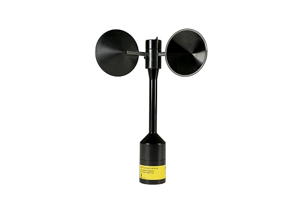
NRG S1 ANEMOMETER
The NRG S1 Anemometer is a class 1 sensor that reduces measurement uncertainty and project cost for wind resource assessment and power performance testing.
The NRG S1 Anemometer is a class 1 sensor that reduces measurement uncertainty and project cost for wind resource assessment and power performance testing.


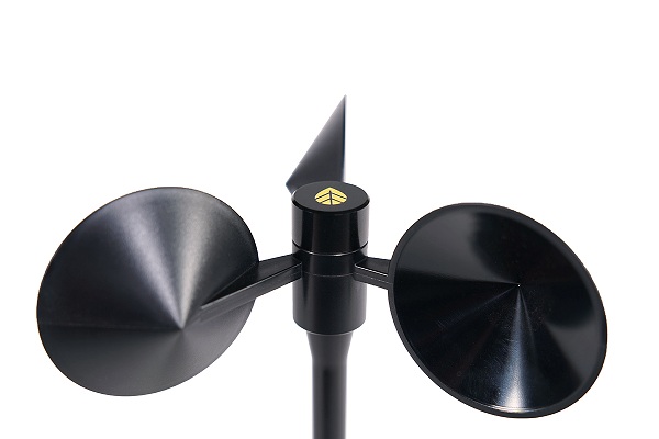
The NRG S1 Anemometer provides a unique balance of high accuracy and low cost, making it ideal for reducing measurement uncertainty in wind resource assessment campaigns as well as power performance tests. A proven bearing system and a rugged, metal body design ensure the sensor will operate reliably for many years, in a variety of environmental conditions.
The NRG S1 Anemometer is the only wind energy anemometer classified to both editions of the IEC 61400-12-1 standard, enabling straightforward comparisons against both new and legacy anemometers.
|
IEC 61400-12-1 |
Edition 1 (2005) |
Edition 2 (2017) |
|
Class A |
1.21 |
1.27 |
|
Class B |
3.86 |
4.19 |
|
Class C |
N/A |
4.15 |
|
Class D |
N/A |
6.13 |
View NRG S1 classification report for IEC 61400-12-1 Edition 1.0 (SOH Wind Engineering LLC)
View NRG S1 classification report for IEC 61400-12-1 Edition 2.0 (SOH Wind Engineering LLC)
More than 60 NRG S1 Anemometers have been field-tested for over a year across a variety of real-world sites. DNV GL has performed an independent verification of the S1 field test. If you are interested in reviewing their technical note, or performing your own analysis of the underlying field test data, please click on the following link:
NRG conducted lightning surge testing which showed that the S1 Anemometer’s resistance to damage from surges in electrical current is superior to the other tested class 1 anemometers commonly used in the wind energy industry.
The NRG S1 Anemometer has also been tested extensively to confirm IEC and CE compliance, as well as IP55 ingress protection, the highest IP standard achievable for cup anemometers.
| MEASNET Calibrated (#9405) | MEASNET Calibrated, SOH CPH (#9415) | MEASNET Calibrated, DWG (#9416) | MEASNET Calibrated (2) (#14363) | MEASNET Calibrated, SOH CPH (2) (#14364) | MEASNET Calibrated, DWG (2) (#14365) | |
|---|---|---|---|---|---|---|
| Description | ||||||
| Sensor type | 3-Cup Anemometer | 3-Cup Anemometer | 3-Cup Anemometer | 3-Cup Anemometer | 3-Cup Anemometer | 3-Cup Anemometer |
| Applications |
|
|
|
|
|
|
| Sensor range | 0.638 m/s to 75 m/s (1.427 mph to 167.8 mph) | 0.638 m/s to 75 m/s (1.427 mph to 167.8 mph) | 0.638 m/s to 75 m/s (1.427 mph to 167.8 mph) | 0.638 m/s to 75 m/s (1.427 mph to 167.8 mph) | 0.638 m/s to 75 m/s (1.427 mph to 167.8 mph) | 0.638 m/s to 75 m/s (1.427 mph to 167.8 mph) |
| Instrument compatibility | All NRG Systems Data Loggers | All NRG Systems Data Loggers | All NRG Systems Data Loggers | All NRG Systems Data Loggers | All NRG Systems Data Loggers | All NRG Systems Data Loggers |
| Measurement range | 0.6 to 75 m/s | 0.6 to 75 m/s | 0.6 to 75 m/s | 0.6 to 75 m/s | 0.6 to 75 m/s | 0.6 to 75 m/s |
| Output signal | ||||||
| Signal type |
Form: Square Wave Frequency: 532.9 Hz @ 50 m/s (112 mph) Amplitude: Equal to supply voltage, max. 15 V |
Form: Square Wave Frequency: 532.9 Hz @ 50 m/s (112 mph) Amplitude: Equal to supply voltage, max. 15 V |
Form: Square Wave Frequency: 532.9 Hz @ 50 m/s (112 mph) Amplitude: Equal to supply voltage, max. 15 V |
Form: Square Wave Frequency: 532.9 Hz @ 50 m/s (112 mph) Amplitude: Equal to supply voltage, max. 15 V |
Form: Square Wave Frequency: 532.9 Hz @ 50 m/s (112 mph) Amplitude: Equal to supply voltage, max. 15 V |
Form: Square Wave Frequency: 532.9 Hz @ 50 m/s (112 mph) Amplitude: Equal to supply voltage, max. 15 V |
| Linearity | Refer to R^2 value on individual calibration report. | Refer to R^2 value on individual calibration report. | Refer to R^2 value on individual calibration report. | Refer to R^2 value on individual calibration report. | Refer to R^2 value on individual calibration report. | Refer to R^2 value on individual calibration report. |
| Anemometer Transfer Function |
|
|
|
|
|
|
| Calibration |
Each anemometer individually calibrated at SOH WE, Williston, VT USA. Calibration reports provided via electronic download. |
Each anemometer individually calibrated at SOH CPH, Copenhagen, DK. Calibration reports provided via electronic download. |
Each anemometer individually calibrated at DWG, Varel, DE. Calibration reports provided via electronic download. |
| Output signal range | 0 Hz to 800 Hz | 0 Hz to 800 Hz | 0 Hz to 800 Hz | 0 Hz to 800 Hz | 0 Hz to 800 Hz | 0 Hz to 800 Hz |
| Resolution | 0.046 m/s | 0.046 m/s | 0.046 m/s | 0.046 m/s | 0.046 m/s | 0.046 m/s |
| Uncertainty |
IEC 61400-12-1 Ed. 1 Classification
|
IEC 61400-12-1 Ed. 1 Classification
|
IEC 61400-12-1 Ed. 1 Classification
|
IEC 61400-12-1 Ed. 1 Classification
|
IEC 61400-12-1 Ed. 1 Classification
|
IEC 61400-12-1 Ed. 1 Classification
|
| Response characteristics | ||||||
| Threshold | 0.638 m/s (1.427 mph) per ASTM D 5096-02 | 0.638 m/s (1.427 mph) per ASTM D 5096-02 | 0.638 m/s (1.427 mph) per ASTM D 5096-02 | 0.638 m/s (1.427 mph) per ASTM D 5096-02 | 0.638 m/s (1.427 mph) per ASTM D 5096-02 | 0.638 m/s (1.427 mph) per ASTM D 5096-02 |
| Distance constant (63% recovery) | 2.76 m (9.05 ft) per ASTM D 5096-02 | 2.76 m (9.05 ft) per ASTM D 5096-02 | 2.76 m (9.05 ft) per ASTM D 5096-02 | 2.76 m (9.05 ft) per ASTM D 5096-02 | 2.76 m (9.05 ft) per ASTM D 5096-02 | 2.76 m (9.05 ft) per ASTM D 5096-02 |
| Moment of inertia |
|
|
|
|
|
|
| Power requirements | ||||||
| Supply voltage | 5 to 28 VDC | 5 to 28 VDC | 5 to 28 VDC | 5 to 28 VDC | 5 to 28 VDC | 5 to 28 VDC |
| Supply current | 0.9 mA at 12V | 0.9 mA at 12V | 0.9 mA at 12V | 0.9 mA at 12V | 0.9 mA at 12V | 0.9 mA at 12V |
| Installation | ||||||
| Mounting | Onto a 25 mm (1") diameter mast with 2 set screws | Onto a 25 mm (1") diameter mast with 2 set screws | Onto a 25 mm (1") diameter mast with 2 set screws | Onto a 25 mm (1") diameter mast with 2 set screws | Onto a 25 mm (1") diameter mast with 2 set screws | Onto a 25 mm (1") diameter mast with 2 set screws |
| Tools required | 2.5 mm Allen Key | 2.5 mm Allen Key | 2.5 mm Allen Key | 2.5 mm Allen Key | 2.5 mm Allen Key | 2.5 mm Allen Key |
| Environmental | ||||||
| Operating temperature range | -30 °C to 60 °C (-22 °F to 140 °F) | -30 °C to 60 °C (-22 °F to 140 °F) | -30 °C to 60 °C (-22 °F to 140 °F) | -30 °C to 60 °C (-22 °F to 140 °F) | -30 °C to 60 °C (-22 °F to 140 °F) | -30 °C to 60 °C (-22 °F to 140 °F) |
| Operating humidity range | 0 to 100% RH | 0 to 100% RH | 0 to 100% RH | 0 to 100% RH | 0 to 100% RH | 0 to 100% RH |
| Lifespan | > 2 years at most sites | > 2 years at most sites | > 2 years at most sites | > 2 years at most sites | > 2 years at most sites | > 2 years at most sites |
| Physical | ||||||
| Connections | M12 Connector | M12 Connector | M12 Connector | M12 Connector | M12 Connector | M12 Connector |
| Cable length | Various available | Various available | Various available | Various available | Various available | Various available |
| Weight | Sensor weight = 190 grams (0.42 lbs) | Sensor weight = 190 grams (0.42 lbs) | Sensor weight = 190 grams (0.42 lbs) | Sensor weight = 190 grams (0.42 lbs) | Sensor weight = 190 grams (0.42 lbs) | Sensor weight = 190 grams (0.42 lbs) |
| Dimensions |
|
|
|
|
|
|
| Materials | ||||||
| Cups | One piece injection-molded black polycarbonate | One piece injection-molded black polycarbonate | One piece injection-molded black polycarbonate | One piece injection-molded black polycarbonate | One piece injection-molded black polycarbonate | One piece injection-molded black polycarbonate |
| Body | Anodized Aluminium | Anodized Aluminium | Anodized Aluminium | Anodized Aluminium | Anodized Aluminium | Anodized Aluminium |
| Shaft | Stainless Steel | Stainless Steel | Stainless Steel | Stainless Steel | Stainless Steel | Stainless Steel |
| Bearing | Ball Bearings | Ball Bearings | Ball Bearings | Ball Bearings | Ball Bearings | Ball Bearings |
| Signal generator | Optical Switch | Optical Switch | Optical Switch | Optical Switch | Optical Switch | Optical Switch |